Week 6 Blog
Operational Amplifiers
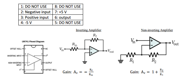 |
| Figure 1: Image of IC chip, and schematics of (Non)-Inverting Amplifiers |
 |
| Figure 1a) An OP-AMP cannot exceed the supply voltage, in this case +5 V and -5 V. This is illustrated by the orange line. However, since ideal measurements are only theoretical, our measured values only were at -3.6 and +4.5 V. The other main difference between our measured and ideal values is that, because the gain is so high, the graph looks like a vertical line at 0. At 0, our DMM read -3.6 V. |
~~b. Apply 0 V to the non-inverting input. Sweep the inverting input (Vin) from -5 V to 5 V with 1 V steps. Take more steps around 0 V (both positive and negative). Create a table for Vin and Vout. Plot the data (Vout vs Vin). Discuss your results. What would be the ideal plot?
 |
| Figure 1b) As you can see, this graph is essentially the reverse of Figure 1a. This makes sense because the circuit was mostly the same, except for the fact that our input voltage was connected to the inverting input. The same still holds true for the limits of the output voltage. However, at 0 our DMM read 4.54 V. The fact that no OP-AMP is ideal is why the orange and blue lines are not the same. |
2. Create a non-inverting amplifier. (R2 = 2 kΩ, R1 = 1 kΩ). Sweep Vin from -5 V to 5 V with 1 V steps.
Create a table for Vin and Vout. Plot the measured and calculated data together.

3. Create an inverting amplifier. (Rf = 2 kΩ, Rin = 1 kΩ). Sweep Vin from -5 V to 5 V with 1 V steps. Create a table for Vin and Vout. Plot the measured and calculated data together.

4. Explain how an OPAMP works. How come is the gain of the OPAMP in the open loop configuration too high but inverting/non-inverting amplifier configurations provide such a small gain?
~~The OPAMP works by using two inputs (+ and -) to receive electricity. If more voltage goes through into the + than the - then it outputs as much voltage as it can. Visa Versa, if more voltage enters into the - than the + then it outputs no voltage.
~~The OPAMP in the open loop has a gain much higher than the inverting/non-inverting configuration. If we simply look at the equations we see
*These are the numbers we got when running this experiment

 |
| Figure 1c) Our calculated values show what an ideal non inverting OP-AMP graph would look like. As you can see the values we measured were higher/lower than ideal, which is what one would expect. The gain for this circuit was 3. |
3. Create an inverting amplifier. (Rf = 2 kΩ, Rin = 1 kΩ). Sweep Vin from -5 V to 5 V with 1 V steps. Create a table for Vin and Vout. Plot the measured and calculated data together.
 |
| Figure 1d) Our calculated values show what an ideal inverting amp graph would look like. As you can see the values we measured were lower/higher than ideal, which is what one would expect. The gain for this circuit was -2. As the name indicates, an inverting amplifier takes a negative input voltage and outputs a positive voltage, and vice versa. |
4. Explain how an OPAMP works. How come is the gain of the OPAMP in the open loop configuration too high but inverting/non-inverting amplifier configurations provide such a small gain?
~~The OPAMP works by using two inputs (+ and -) to receive electricity. If more voltage goes through into the + than the - then it outputs as much voltage as it can. Visa Versa, if more voltage enters into the - than the + then it outputs no voltage.
~~The OPAMP in the open loop has a gain much higher than the inverting/non-inverting configuration. If we simply look at the equations we see
Open loop gain: ( Vout )/( V+ - V- )
Inverting gain: -(Rf / Rin)
Non-inverting gain:1+ (R2 / R1)
***REFER TO FIGURE 1 FOR DETAILS PERTAINING TO THE RESISTORS***
~~Generally the reason why the gain is smaller is because the resistors dampen the abilities to produce higher gain.
Temperature Controlled LED System
1. Connect your DC power supply to pin 2 and ground pin 5. Set your power supply to 0V. Switch
your multimeter to measure the resistance mode; use your multimeter to measure the
resistance between pin 4 and pin 1. Do the same measurement between pin 3 and pin 1. Explain
your findings (EXPLAIN).
Vin
|
Pins 1 to 3
|
Pins 1 to 4
|
0 V
|
0.953
|
OL
|
1 V
|
0.949
|
OL
|
2 V
|
0.961
|
OL
|
3 V
|
0.959
|
OL
|
4 V
|
0.976
|
OL
|
5 V
|
0.996
|
OL
|
6 V
|
OL
|
0.960
|
7 V
|
OL
|
0.962
|
8 V
|
OL
|
0.963
|
2. Now sweep your DC power supply from 0V to 8V and back to 0V. What do you observe at the
multimeter (resistance measurements similar to #1)? Did you hear a clicking sound? How many
times? What is the “threshold voltage values” that cause the “switching?” (EXPLAIN with a
VIDEO).
*Further explaination: For pins 1 to 3 and pins 1 to 4 the multimeter was reading the same as number 1. I heard 4 clicks when I did the operation for both trials. The clicks closer to the 0V was a deeper click and the clicks closer to the 8V had a higher toned pitch. The Threshold voltage is about 6 voltages when it energizes and then about 2 V is the lower side when it de energized.
Video explaining how the relay clicks during energizing and de-energizing phases
*Further explaination: For pins 1 to 3 and pins 1 to 4 the multimeter was reading the same as number 1. I heard 4 clicks when I did the operation for both trials. The clicks closer to the 0V was a deeper click and the clicks closer to the 8V had a higher toned pitch. The Threshold voltage is about 6 voltages when it energizes and then about 2 V is the lower side when it de energized.
3. How does the relay work? Apply a separate DC voltage of 5 V to pin 1. Check the voltage value
of pin 3 and pin 4 (each with respect to ground) while switching the relay (EXPLAIN with a
VIDEO).
Video explaining how a relay works as a switch and an amplifier
|
Pin 3
|
Pin 4
|
|
1.2 ohms
|
1.1 ohms
|
|
OL
|
OL
|
LED + Relay


1. Connect positive end of the LED diode to the pin 3 of the relay and negative end to a 100 ohm
resistor. Ground the other end of the resistor. Negative end of the diode will be the shorter
wire.
2. Apply 3 V to pin 1
3. Turn LED on/off by switching the relay. Explain your results in the video. Draw the circuit
schematic (VIDEO)
Video showing how the relay is amplifying the signal to power the LED

This is the schematic of our LED+Relay Circuit.
Operational Amplifier
1. Connect the power supplies to the op-amp (+10V and 0V). Show the operation of LM 124
operational amplifier in DC mode with a non-inverting amplifier configuration. Choose any
opamp in the IC. Method: Use several R1 and R2 configurations and change your input voltage
(voltages between 0 and 10V) and record your output voltage. (EXPLAIN with a TABLE)
Input
|
Output (R1= 100 ohm, R2=100 ohm)
|
Output (R1= 1000 ohm, R2=100 ohm)
|
Output (R1= 1200 ohm, R2=100 ohm)
|
1
|
1.3
|
1.8
|
2.1
|
5
|
4.91
|
6.33
|
6.8
|
7
|
7.6
|
7.7
|
7.9
|
*Table displaying our results from the op-amp experiment
2. Use your temperature sensor as your input. Do you think you can generate enough voltage to
trigger the relay? (EXPLAIN)
*CAN'T DO NO TEMPERATURE SENSOR TO USE.
But if we had to hypothesize then no I don't believe our temperature sensor alone can trigger our relay, because it won't have enough voltage to it.
*CAN'T DO NO TEMPERATURE SENSOR TO USE.
But if we had to hypothesize then no I don't believe our temperature sensor alone can trigger our relay, because it won't have enough voltage to it.
3. Design a system where LED light turns on when you heat up the temperature sensor. (CIRCUIT
schematic and explanation in a VIDEO)
*CAN'T DO NO TEMPERATURE SENSOR TO USE.
But if we had to only draw the circuit out this is what we would get started with below:
*Note we didn't include the voltages or the resistance, because without trying the circuit we don't actually know the real numbers to it. So we just labeled everything ambiguously (V1,V2 and R1).

Your explanation for #4 of the OPAMP was very simple and helped me better understand the reason the resistors in the OPAMP circuit cause the gain to be lower than in open loop configuration. My best guess was that the resistors caused a voltage drop going back into the OPAMP and would a smaller difference between the two voltages.
ReplyDeleteThank you for the comment. The OPAMP confused me for a while, because I was understanding what was going on at first, at first I was way over thinking it. The first part of the lab was very laborious for us because we were over thinking it so much.
Deletei think you didn't finish your blog, so i have noticed you have a good explanation for question #4. Also, your videos are good so don't miss the captions for it.
ReplyDeleteAll your videos provided a very good overview about what is going on in the video. I really liked the explanations. As other people have said, #4 stood out. Overall, we had a lot of the same values and outputs. This stuff with gain, has really confused me on some parts, but it seems like you have a great handle on it. Good job guys!
ReplyDeleteYou might want to make the table bigger for number 1 and 2 as they are kinda hard to see but in terms of the values, ours were a lot less consistent compared to yours. Also your videos were very nice. This week went pretty smooth for us, did you guys have any issues?
ReplyDeleteFor your non - inverting amplifier you ended up getting a better graph than us because we didn't take measurements that close to zero, but we definitely should have. Also I like the way that you did your videos, they are really close to the breadboard and they look good. We ended up having to redo our circuit in the beginning because we didn't realize that the view of the relay was from the top of it upside down, I don't know if you had the same problem with that but we did at first :( Also, did you test to see if the LED would get brighter with a lower or higher resistance? We did and nothing happened....
ReplyDeleteYour tables for 1 and 2 are very hard to read may want to enlarge them. Other than that our values are close and you do a good job with your videos.
ReplyDeleteYou mentioned that a relay works by opening and closing a switch. What is the difference between these two settings in terms of how the relay behaves in the circuit and how the various pins are effected?
ReplyDeleteYour explanation in Q3 for how the relay works was pretty good but I think you need to add some explanation for the second part which is to check the voltage value of pin 3 and pin 4 and what happens to the two pins when the switch occurs at 6V and 2V. other than that, your blog is well explained.
ReplyDeleteYour graphs are very tiny and hard to read. I would consider making them vertical so it is easier to read. Your graphs, however, are nice and large and easy to see. Your data seems to be on par with ours and others in the class. You should show some other components of the circuit in your clicking video. It doesn’t really show what the thresholds are, just shows that it does click. Don’t forget to include a circuit diagram for the end of the blog, even though we can’t build the circuit. Your video on the LED was well put together.
ReplyDeleteFrom you graph I thik you have same results as me group.
ReplyDeleteI suggest you to add tables to Q# 1,2 and 3, to make you result much clearer to any reader.
Also you missed to finish the last part of the experiment. Otherwise everything are good.
Good job
The formatting needs some more whitespace in between your questions. the tables should be done more vertical, rather than horizontal (it's easier to read). It's interesting to see the captions the way they are. Your answer for #4 was very helpful, we didn't know the equation for open-loop configuration existed. You're missing some written explanations (#1 on Temp controlled LED system). Nice short videos!
ReplyDeleteI love how you guys setup your graphs and data tables this week, although I feel like it would help if the graphs were vertical instead of horizontal in order to make it easier for us to read them. The values you guys got were pretty similar to ours, and the videos are very clear to understand. Remember to include the circuit diagram and you guys are good to go.
ReplyDeleteVery well done work. On your circuit diagram on part 3 of the last section, you may want to add a parenthetical citation saying where you got that image from for your relay.
ReplyDeleteVery well done work. On your circuit diagram on part 3 of the last section, you may want to add a parenthetical citation saying where you got that image from for your relay.
ReplyDeleteVery hard to read the table. Even when I try to make it bigger. However, our data was not very close to yours. Everything else was well organized and clear. Good Job.
ReplyDeleteLimited responses to comments. Otherwise, good blog.
ReplyDeleteWe got similar values for question 1 a and b but do you have any theory why our values don't span to the theoretical boundaries of -5 and positive 5 and on that note dont even appear to be symmetrical?
ReplyDeleteThank you so much for sharing this great blog.Very inspiring and helpful too.Hope you continue to share more of your ideas.I will definitely love to read. Electronic Components
ReplyDelete